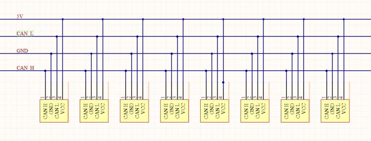
My purpose is connecting many devices via CAN BUS. This is the initial circuit schematic diagram. I hope to connect 8 CAN devices to the same HUB. Can you see any problem with this design ? As well as 5V power input to HUB will give from outside.
Generally, star topologies are not recommended for CAN due to associated problems with signal reflections. This is not to say that it wouldn’t work but you should be ready to face signal integrity issues, especially with large high-speed networks. Consider connecting your nodes in a linear bus instead (like a daisy chain).
It is not recommended to use any kind of hubs on UAVCAN bus because it is supposed to be daisy-chained and all UAVCAN devices shoukd have 2 can connectors per bus(one for input and one for output). This will guarantee that wire stubs are minimal and the bus may be longer without signal degradation.
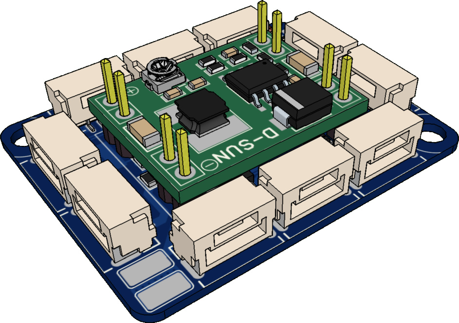
Also, speaking about the existing HUB, this device allows for 3 assembly variants.
And part GW1584(which is a cheap dc-dc module) is there to provide UAVCAN bus with 5V@3A power rail from VBAT(up to 6S). It is totally optional
All the MCU part may be there for CAN bus power consupmtion and voltage monitoring. This part is optional as well…
I have just understood what you were asking about.
R8 R9 R10 in the schematic have invalid values. These resistors should form a current shunt for UAVCAN bus consumption measurement(with ADC_IN1) and C12 is there for some basic filtering.
R8-R10 values should be somewhere in 1-10 ohms(we should use ohm’s law for that)