We will have to do a lot of testing to get the Viper quadcopter flying and to 107-Arduino-UAVCAN library. So we need a proper test system. I think most of the users here use a computer or a notebook and some type of slcan adapter.
I didn’t want to risk to corrupt my working system by installing lots of software so I decided to use a Raspberry Pi and set up the system there. There are some CAN boards on the market but most of them use a MCP2515 CAN controller which has no CAN FD and they also don’t have the connector specified by the dronecode standard.
That’s why my first step was to design a new HAT with the MCP2518FD controller. This controller supports CAN FD and it is has also drivers in the mainline raspbian distribution.
This is how the board looks in CAD:

The board has only a few components:
- the MCP2518FD CAN controller
- a TCAN332 CAN transceiver which also supports CAN FD
- a switch to enable the termination resistor
- the JST GH connectors
- a terminal header to connect other CAN devices
- and a few LEDs to show the status
In reality it looks like this:
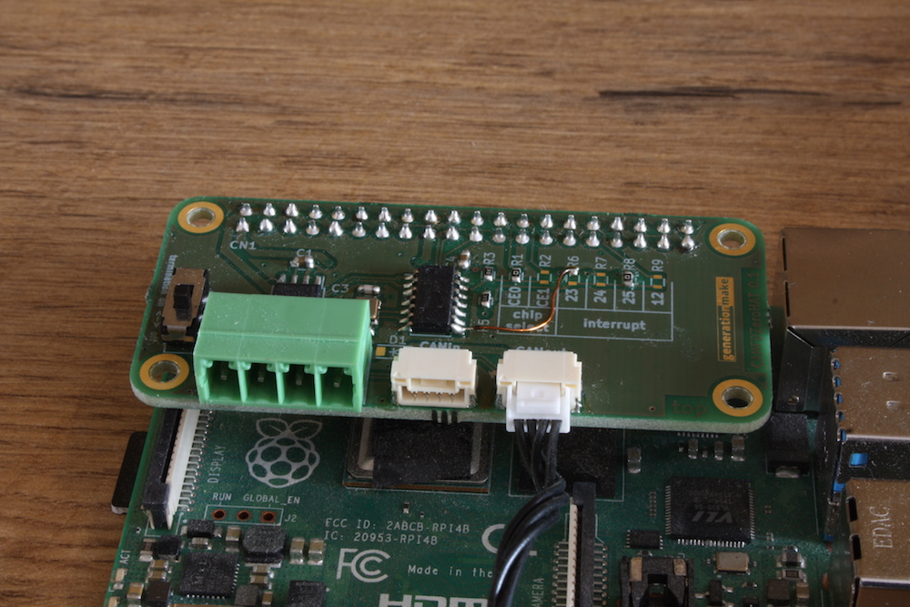
It plugs directly ontop of a Raspberry Pi. In my case I used a Raspberry Pi 4.
The HAT is open source hardware and all the data is available on github:
To enable the HAT and the CAN controller in raspbian you simply have to edit /boot/config.txt and add line:
dtoverlay=mcp251xfd,spi0-0,oscillator=20000000,interrupt=25
keep care that you choose the right interrupt and SPI CE line and populate the corresponding resistor.
To enable CAN after boot up you have to enter:
sudo ip link set can0 up type can bitrate 250000
And that’s it. Now the interface is available as can0. You can show all CAN traffic by typing candump -decaxta can0 or use yakut to transmit and receive UAVCAN messages.
The whole test setup with DUT looks like this:
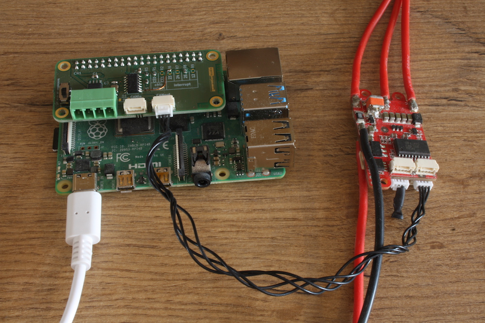
The Raspberry Pi can be accessed via WiFi so no more cables are necessary. You could also use cable LAN or directly connect a screen and a keyboard.
The HAT has also the possibility to supply power into the CAN systems. So small sensor nodes wouldn’t even require additional wiring.
I hope this helps to setup a proper test environment.
But I also have to confess that there is still a little problem: it seems like the MCP2518FD is sometimes missing some frames. Especially when there is a high load on the system. Maybe the receive interrupt isn’t handled properly. I will have to dig deeper into that but I think this could be only a minor issue.